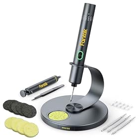
QFNs are difficult to solder with a conventional iron because most of their connections sit underneath the package. Hot-air rework heats the package and surrounding pads more evenly, making it the better choice for removing or replacing many QFNs. An iron is still useful for touch-up, pad preparation, and some small exposed-edge connections—but dragging a tip around the package is rarely a reliable primary method.
Why QFNs are hard to solder with an iron
A QFN typically has perimeter pads hidden beneath the body, plus a central exposed pad on some versions. After the package is placed, the solder joints are not visible from above.
An iron can struggle because:
- The tip cannot directly reach most of the joints.
- Heat is applied unevenly around the package.
- Pulling or pushing the package can smear solder bridges underneath it.
- Excessive tip contact can lift small PCB pads or damage the package.
- The center thermal pad may not receive enough heat to reflow properly.
An iron can sometimes solder a QFN if the board design exposes pads at the edges, but that is a special case rather than a general replacement for hot air.
When hot air is the better alternative
Use hot-air rework when you need to remove a QFN, replace a misaligned package, reflow a package with hidden joints, or work on a board where the component cannot be accessed from the opposite side.
Hot air is especially useful for:
- Replacing damaged or incorrectly installed QFNs
- Reflowing a package after applying solder paste
- Removing a QFN without levering against the PCB
- Heating an exposed center pad and the perimeter pads at the same time
- Repairing boards with dense surrounding components
The main advantage is not simply higher temperature. It is the ability to distribute heat across the package and nearby pads without forcing a metal tip into hidden joints.
Hot air versus an iron for QFN work
| Task | Hot-air rework | Soldering iron |
|---|---|---|
| Remove a QFN | Usually the better choice | Poor fit for most QFNs |
| Place a new QFN | Good with paste and alignment | Limited and difficult |
| Touch up visible edge pads | Possible, but less precise | Usually better |
| Rework a single accessible pad | Often excessive | Usually better |
| Heat an exposed center pad | More even heating | Difficult after placement |
| Protect nearby parts | Requires airflow and shielding control | Easier in a small area |
The most practical setup often uses both tools: hot air for removal and main reflow, then a fine-tip iron for accessible cleanup or repair.
A practical hot-air QFN rework process
1. Confirm the package and board layout
Check the component drawing and PCB footprint before applying heat. Verify the pin-1 marking, package orientation, pad layout, and whether the board includes a center thermal pad.
If the part has an exposed pad, the amount and placement of solder underneath it matter. Too much solder can lift the package or create an unreliable joint; too little can reduce thermal or electrical contact.
2. Protect nearby components
Remove loose plastic items and shield heat-sensitive parts near the work area. Kapton tape, metal shields, or other suitable barriers can help, but shielding must not trap excessive heat against the board.
Avoid directing hot air at connectors, switches, displays, batteries, or unprotected plastic components unless their manufacturer allows it.
3. Apply flux and use the right consumable
For replacement work, clean the old pads and apply a controlled amount of flux. New solder paste is generally easier to control than adding a large amount of solder wire beneath a hidden package.
Use paste and flux appropriate for the board, component, and reflow process. Solder alloy affects the required heat profile, so do not copy a temperature blindly from another job.
4. Align the package before heating
Place the QFN carefully using the pin-1 indicator and the PCB footprint. With small packages, magnification is valuable. The package should sit squarely on the pads before reflow begins.
5. Heat gradually
Use a nozzle that covers the package without unnecessarily blasting the surrounding board. Start with moderate airflow and bring the board and solder up to temperature gradually. The correct temperature and dwell time depend on the solder alloy, board mass, package, and the component manufacturer’s limits.
Do not rely only on the number shown on the station. The temperature at the package can differ from the displayed setting, and high airflow can move small components or blow molten solder away.
6. Watch for reflow, not movement by force
When the solder melts, the package may settle slightly. Do not push it around aggressively. If alignment is wrong, stop heating, let the area cool, and correct the process rather than dragging the package across molten solder.
Never pry up a QFN while the joints are partly molten. That can tear pads from the PCB.
7. Inspect the result
Because the joints are hidden, inspection requires more than looking at the top of the package. Check for:
- Correct orientation and package position
- Solder squeeze-out or unexpected movement
- Bridges at exposed edges
- Shorts between adjacent pins using appropriate electrical checks
- Continuity and resistance to ground where the circuit design permits
- Proper operation of the repaired circuit
For critical or production work, X-ray inspection may be needed to verify hidden joints and the center pad. A visual inspection alone cannot confirm every connection under a QFN.
When an iron is still the better tool
Hot air is not automatically the right answer for every QFN-related repair. Use an iron when you need to:
- Tin or clean an exposed PCB pad before replacement
- Repair a clearly accessible edge pad
- Remove excess solder from a visible bridge
- Attach a wire to an exposed test point or pad
- Perform a small correction without heating nearby components
A fine tip, appropriate flux, and magnification can make these jobs much easier. Keep contact brief and avoid using the tip as a lever against the package or board.
Common hot-air mistakes
Excessive airflow
Too much airflow can move the QFN, displace tiny nearby parts, or spread molten solder. Lower airflow is often easier to control, especially on densely populated boards.
Excessive heat or dwell time
Long heating can delaminate the PCB, damage the component, oxidize pads, or weaken nearby solder joints. Follow the component and solder manufacturer’s guidance where available.
Heating only the package
A large temperature difference between the package and PCB can create poor reflow or thermal stress. Gradual heating and, when appropriate, board preheating can produce a more controlled process.
Using too much solder paste
More solder does not compensate for poor alignment. Excess paste can cause bridges, lift the package, or interfere with the exposed center pad.
Skipping cleaning and inspection
Flux residue, old solder, and debris can affect alignment and electrical performance. Clean according to the flux manufacturer’s instructions, then inspect under magnification.
What equipment makes the switch worthwhile?
A hot-air station with adjustable temperature and airflow is the main tool. Useful features include a stable handpiece, interchangeable nozzles, a way to return the handpiece safely, and controls that are easy to adjust while viewing the board.
You may also need:
- A fine-tip soldering iron for pad cleanup and touch-up
- Flux suitable for the soldering process
- Solder paste or controlled solder wire
- Tweezers and magnification
- Kapton tape or suitable heat shielding
- A temperature-aware work method, such as a thermocouple, for sensitive or repeatable work
A hot-air tool does not remove the need for an iron. It changes which tool handles the main heating step.
When to stop and replace the board or seek professional help
Stop if pads lift, the PCB begins to discolor, the package will not reflow within a reasonable process, or nearby parts are becoming excessively hot. Let the board cool before inspecting it.
For multilayer boards, expensive assemblies, leadless packages with fine pitch, or safety-critical electronics, professional rework may be more economical than risking additional damage. Follow the component manufacturer’s reflow limits and use a qualified technician when the board’s function or safety depends on the repair.