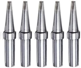
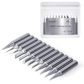
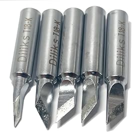
Knife and hoof tips can both drag solder IC leads, but their shapes favor different jobs. Choose a knife tip for directional control and awkward access; choose a hoof tip for smooth solder flow across regular rows of pins.
Knife tip versus hoof tip for drag soldering
For most drag-soldering work, a hoof tip is the easier general-purpose choice, while a knife tip is better when you need directional control, access around obstacles, or a broader contact edge. The right choice depends on the component layout, pin spacing, solder volume, and how precisely you need to steer the molten solder.
Both tips can solder fine-pitch surface-mount leads. Neither eliminates the need for appropriate flux, a clean tip, controlled movement, and a temperature setting suitable for the solder and board.
Quick comparison
| Feature |
Knife tip |
Hoof tip |
| Basic shape |
Flat, angled blade or wedge |
Curved, concave end that holds solder |
| Best strength |
Directional control and access |
Smooth solder transfer along a pin row |
| Solder reservoir |
Usually limited or held along an edge |
Naturally holds a small bead of solder |
| Ideal use |
Crowded boards, connectors, selective drag work |
Fine-pitch IC rows and repeatable drag soldering |
| Handling |
More dependent on orientation and angle |
Generally more forgiving |
| Main risk |
Scraping, uneven contact, or too much solder at the edge |
Carrying too much solder if the bead is oversized |
How the tip shapes affect drag soldering
Drag soldering works by placing a small amount of solder on the tip, applying flux to the joint area, and moving the tip steadily across a row of leads. Surface tension helps distribute solder between the lead and pad.
A hoof tip has a curved or concave working surface. That curve retains a small solder bead, so the tip can supply solder continuously as it travels across the pins. The shape tends to make the motion feel smooth and consistent.
A knife tip has a flatter, more directional edge. You can use the edge, point, or broad face depending on the tip design and the access available. It is useful when you need to approach a row from a particular direction or work around nearby components, shielding, or connectors.
The exact geometry varies between manufacturers. A tip described as a knife or hoof may not have identical dimensions or curvature across brands, so the listed width, angle, and soldering-system compatibility still matter.
When a hoof tip is the better choice
Choose a hoof tip first if your main work involves:
- Fine-pitch ICs with straight, accessible rows of leads
- Repeated drag soldering on similar packages
- Lead-free solder, which often benefits from a steady heat path and good flux coverage
- A controlled solder bead that can travel along several pins
- Learning drag soldering and wanting a forgiving starting shape
The concave end makes it easier to carry solder without repeatedly feeding wire at every pin. With enough flux and a small bead, the tip can glide along the row while leaving solder at the joints.
A hoof tip is not automatically better for every fine-pitch package. If the tip is too wide for the row, too much solder may bridge adjacent pins. Select a working width that fits the lead row and allows the tip to contact the joints without touching nearby components.
When a knife tip is the better choice
A knife tip can be preferable when you need to:
- Approach pins from the side or at a specific angle
- Work near tall components, connectors, or shielding
- Control exactly where the solder contacts the row
- Solder wider leads or tabs with a broad edge
- Remove or redistribute solder bridges with a deliberate wiping motion
- Reach joints where a curved hoof tip does not sit comfortably
The blade-like edge can provide useful directional control. You can orient the tip so its edge follows a row, or use a portion of the face for a larger joint. This flexibility is valuable on crowded boards and irregular layouts.
The tradeoff is that a knife tip may not hold solder as naturally as a hoof tip. You may need to manage the solder amount more carefully and keep the contact angle consistent. Pressing down to compensate for poor wetting can damage pads or drag components out of alignment.
Which tip is easier for fine-pitch ICs?
For a straight row of fine-pitch pins, a small hoof tip is usually the simpler starting point. Its solder-holding shape supports a continuous drag motion and can reduce the need to feed solder during the pass.
A knife tip may be preferable if the package is surrounded by obstructions or if you need to isolate one section of the lead row. It can also work well when the board layout requires a shallow, sideways approach.
Tip width is at least as important as tip type. A tip that is too large can touch adjacent pins, pads, or components. A tip that is too small may transfer heat poorly and require excessive dwell time. Choose the largest tip that fits the joint area without contacting neighboring conductors.
Solder and flux matter more than the shape alone
Neither tip will perform reliably on contaminated or poorly fluxed joints. Before comparing technique, check these basics:
- Apply appropriate flux to the entire lead row.
- Tin the tip lightly rather than covering it with a large blob.
- Align the component so the leads sit correctly on their pads.
- Move at a steady speed instead of stopping on individual pins.
- Inspect for bridges under magnification after the pass.
Use solder that matches your assembly process and the component or board requirements. Lead-free solder generally requires more heat management than traditional leaded solder, but the correct setting depends on the solder alloy, station, tip, board, and manufacturer guidance. Avoid compensating for poor flux or an oxidized tip by continually increasing temperature.
Drag-soldering technique with either tip
1. Secure and align the board
Keep the board stable. Misalignment makes it difficult to maintain a consistent contact angle and can cause the tip to catch on leads.
2. Flux the lead row
Use enough flux to support wetting across the row. Insufficient flux commonly causes uneven solder distribution and bridges.
3. Add a small solder bead
Place a small amount of solder on the working part of the tip. A hoof tip can retain the bead in its curved end; a knife tip may hold it along the edge or on part of the face.
4. Set the contact angle
Touch the tip to the lead-and-pad junction, not just the top of the leads. Keep the angle stable as you begin the pass.
5. Drag smoothly
Move in one controlled motion along the row. Avoid pressing hard or repeatedly reversing direction. If the tip catches, lift it gently, add flux, and reassess the angle rather than forcing it through the pins.
6. Inspect and correct
Use magnification and good lighting. If there is a bridge, add flux and use a clean, lightly tinned tip to draw away excess solder. Desoldering braid may be more appropriate for a stubborn bridge or a large excess of solder.
Common problems and what they usually mean
The hoof tip leaves bridges between every pin
The solder bead may be too large, the tip may be too wide, or the board may not have enough flux. Try a smaller bead, more flux, a slower but continuous pass, or a narrower compatible tip.
The knife tip produces dry or incomplete joints
The edge may not be contacting both the lead and pad, or the tip may be too small to transfer enough heat. Check alignment, add flux, clean and tin the tip, and adjust the angle. Do not press harder as a substitute for proper contact.
Solder sticks to one side of the tip
Oxidation, inadequate tinning, or an inconsistent angle can prevent even wetting. Clean and retin the tip according to the station and tip manufacturer’s instructions. Replace it if the working surface is pitted, worn, or no longer wets properly.
Pads or leads move during the drag
Excessive pressure, too much heat, or a poorly secured component may be responsible. Stop and inspect the joint. If a pad has lifted or a lead has shifted, further heating can make the damage worse.
How to choose the actual replacement tip
Tip shape is only one part of compatibility. Before buying, confirm:
- The tip fits your soldering iron or station series
- The tip width is suitable for the lead row or joint size
- The tip angle matches the access you have around the board
- The tip is intended for your soldering system’s heating and temperature-control design
- The finish and tip construction are appropriate for electronics soldering
A replacement tip that looks similar may not fit correctly or may not transfer heat as intended. Use the iron or station manufacturer’s compatibility information when available.
Bottom line
Choose a hoof tip as the default drag-soldering option for accessible, regular rows of fine-pitch IC leads. Its curved end holds a small solder bead and supports a smooth, repeatable pass.
Choose a knife tip when access, direction, or selective control matters more than carrying a solder reservoir. It is particularly useful around crowded layouts, connectors, and irregular joint patterns.
If you are unsure, a small compatible hoof tip is usually the better first purchase, followed by a knife tip when your board layouts call for more controlled or angled access.