Soldering header pins is straightforward when the pins stay square and the joint receives enough heat. This guide covers setup, technique, inspection, and troubleshooting for development boards.
Soldering header pins onto a development board is easiest when you align the pins first, solder one pin to hold the strip in place, and then work through the remaining pins. Use a temperature-controlled soldering iron with a clean, appropriately sized tip, electronics solder, and a stable way to hold the board.
What you need
- Development board and matching header pins
- Temperature-controlled soldering iron or soldering station
- Clean, tinned tip suitable for the joint size
- Electronics solder, commonly a thin diameter suited to small through-hole joints
- Flux, if the solder does not flow easily or the pads are oxidized
- Tip cleaner or brass wool
- Side cutters for trimming the header after soldering, if needed
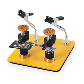
- Helping hands, a vise, or another stable board holder
- Safety glasses and suitable ventilation or a fume extractor
Check the board and header orientation before heating anything. Some boards use different headers on different sides, and installing a strip backward can make the finished board difficult or impossible to connect correctly.
Prepare and align the header pins
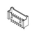
Break or cut the header strip to the required number of pins. If possible, insert the long pins through the board so the plastic spacer rests against the board. This usually leaves the longer pins available for connecting jumper wires or a breadboard.
Place the board flat or hold it securely. Make sure the header is fully seated and that every pin passes straight through its hole. A breadboard can help keep a header strip aligned, but confirm that the board and header are positioned as intended before soldering.
Clean the iron tip and apply a small amount of fresh solder to it. The solder should form a thin, shiny coating rather than a large blob.
Solder the first pin
Choose a pin near one end of the header. Heat both the pin and the copper pad at the same time, then feed a small amount of solder into the heated joint—not directly onto the iron tip.
Remove the solder, then remove the iron. The solder should flow around the pin and form a small concave fillet connecting the pin to the pad. Do not keep heating the joint after the solder has flowed.
Allow the joint to cool for a moment, then check the alignment from several angles. If the header is tilted, reheat that first joint while gently correcting the header position. Do not force the plastic spacer while the solder is solid.
Solder the remaining pins
Once the header is straight, solder the other pins one at a time:
- Place the clean tip against the pin and pad.
- Heat the joint briefly until both surfaces are hot.
- Feed in just enough solder to form a smooth connection.
- Remove the solder, then the iron.
- Let the joint cool without moving the board.
For a typical small through-hole header, the solder should wet the pad and pin without covering the entire surrounding area. Avoid creating a large mound, since excess solder can hide poor wetting or bridge adjacent pins.
Clean the tip between groups of pins if it becomes dull or contaminated. If a joint will not accept solder, add a small amount of flux and try again rather than holding the iron on the board for an extended time.
Inspect the finished joints
A good header-pin joint generally has solder visibly attached to both the pin and the pad, with a smooth transition between them. Check for:
- Pins that are still straight and evenly spaced
- Pads that are completely wetted by solder
- No gaps or cracked-looking joints
- No solder bridges between adjacent pads
- No lifted pads, scorched board material, or damaged plastic
- No loose pins when the header is touched gently after cooling
Use magnification if the pads are small. Also inspect the opposite side of the board if the design has plated through-holes; solder should generally be visible where the pin exits, depending on the board and joint design.
Clean any flux residue according to the solder and board manufacturer's instructions. Some flux is designed to remain, while other residues should be removed with electronics-safe cleaner. Never clean an energized board.
Common problems and fixes
The header is crooked
Reheat the first anchor joint and gently straighten the header. Once several pins are soldered, correcting the angle becomes harder. If the plastic spacer has softened, allow it to cool before handling it.
Solder will not flow onto the pad
The pad or pin may be dirty, oxidized, or insufficiently heated. Clean the tip, add a small amount of flux, and heat the pin and pad together. A tip that is too small may transfer heat poorly, while a heavily oxidized tip may not transfer heat effectively.
The joint looks dull or cracked
The joint may have moved while cooling or may not have been heated evenly. Reapply flux if appropriate, reheat the joint until the solder flows, and keep the board still as it cools.
Two pins are connected by solder
Turn off or unplug the equipment and let the board cool. Remove the excess with solder wick or a suitable desoldering tool, then inspect the pads for damage. Do not scrape aggressively across the board.
The pad lifts from the board
Stop heating the area. A lifted pad can sometimes be repaired, but the correct repair depends on whether the electrical trace and plated hole are still intact. For an important board, consult an experienced electronics repair technician rather than repeatedly reheating it.
Choosing the iron and solder
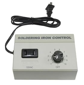
A temperature-controlled soldering station is easier to use than an unregulated iron because it helps maintain consistent heat as the joint draws heat away. Look for a station with replaceable tips and a tip shape that can contact both the pin and pad.
A small chisel or bevel tip is often easier for header pins than an extremely fine pointed tip because it transfers heat through a broader contact area. The correct tip still depends on the board size, pad layout, and the header being installed.
Use solder intended for electronics, not plumbing solder or acid-core solder. Choose a diameter that lets you add small, controlled amounts. Lead-free solder generally requires closer attention to heat, wetting, and cleanliness than leaded solder; follow the solder manufacturer's guidance and provide effective ventilation.
When to replace a tool or use a different method
Replace a soldering tip if it is deeply pitted, no longer holds solder, or remains badly oxidized after proper cleaning and tinning. Replace solder if it is contaminated or difficult to feed consistently.
If the board repeatedly overheats, pads lift, or joints fail despite proper preparation, stop and verify the iron's temperature control, tip condition, solder type, and technique. A stable board holder and better-matched tip may solve the problem. For damaged traces, multilayer boards, or costly development hardware, professional repair is safer than repeated rework.